MoE-Lightning: High-Throughput MoE Inference on Memory-constrained GPUs
Systor 2024
Shiyi Cao, Ion Stoica
UC Berkeley
Background
Despite their advantages, the widespread use of MoE models faces challenges due to the difficulties in managing and deploying models with extremely high parameter counts that demand substantial memory. This work aims to make MoE models more accessible to those lacking extensive high-end GPU resources.
Performance Analysis
Hierarchical Roofline Model (HRM)
- extends the classical Roofline Model for multicore architectures
- use to conduct a theoretical performance analysis for MoE inference.
- the turning points define the computation is best done on CPU / GPU
Compute Roof:
- Represents the processor’s maximum computational capability (FLOPs/s).
- processors at different levels (CPUs / GPUs) have different computational capability
Memory Roof:
- Represents the limitation of memory bandwidth
- Memory bandwidth (Bytes/s) × Operational intensity (FLOPs/Bytes) = Performance upper bound (FLOPs/s)
- HRM also introduces cross-layer memory ceilings : memory bandwidth from CPU to GPU (PCIe)
𝑃_𝑖 = min(𝑃_compute, 𝑃_memory, 𝑃_cross-layer)
Case Study
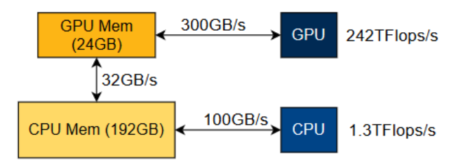
Serving Mixtral 8x7B model on a Google Cloud Platform L4 instance
Attention Block
Vertical lines: different operational intensities for the attention computation with different KV cache data types.
Both float16 and int4’s intensity are quite low and smaller than 𝑃1’s corresponding intensity, so it may be better to perform attention on CPU.
- Theoretically, attention’s operational intensity is independent of the batch size since its flops and bytes are proportional to batch size.
- To increase the attention computation’s operational intensity, methods such as quantization, Grouped Query Attention (GQA), or sparse attention are used to reduce the memory access needed in attention computation.

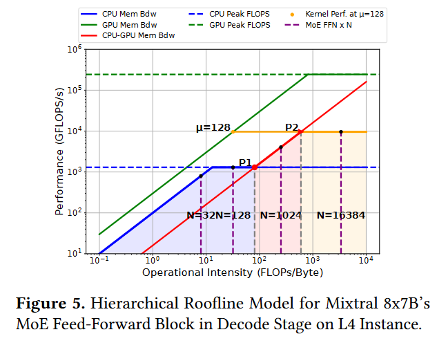
MoE Feed-Forward Network (FFN)
The orange line represents the MoE FFN kernel performance achieved at a micro-batch size of 128.
Vertical lines intersecting with CPU roofs and CPU-GPU memory roofs represent different batch sizes.
- FFN’s operational intensity will increase as batch size or micro-batch size increases since a larger batch size means more computation per weight access. 不理解为什么这里有关上面无关
- suppose the computation kernel for the MoE FFN can run at a maximum 𝜇 = 128 (micro-batch:Since GPU memory is limited, a batch of size 𝑁 often needs to be split into several micro-batches of size 𝜇 to be processed by a single kernel execution on GPU.)
When 𝐼 is less than 𝑃1’s corresponding 𝐼 , there is no benefit in swapping the data to GPU for computation since it will be bounded by the memory roof from CPU to GPU. This is normally the case for many latency-oriented applications where users may only have one or two prompts to be processed. In such scenarios, it is more beneficial to have a static weights placement strategy (e.g., putting 𝑚 out of 𝑛 layers on GPU) and perform the computation where the data is located instead of swapping the weights back and forth 为什么这里’more beneficial’放GPU,不应该和attention一样吗,放GPU也被GPU带宽限制.
Next, When 𝐼 is less than 𝑃2’s corresponding 𝐼 , the computation is bounded by the CPU to GPU memory bandwidth, and it cannot achieve the performance at 𝑃2. Depending on whether there is enough CPU memory to hold a larger batch, we can either increase the batch size or put some of the weights on the GPU statically since both srategies can increase the operational intensity for the MoE FFN computation.
If the batch size can be continually increased, then when 𝐼 equals 𝑃2’s corresponding 𝐼 , the maximum performance that can be achieved is bounded by the operator’s operational intensity on GPU, which is dependent on the 𝜇 for the MoE FFN kernels. Then, there is no need to increase 𝑁 anymore, and the maximum performance reached at a balance point equals 𝑃2. On the other hand, if we put more weights onto GPU, 𝜇 will decrease since larger 𝜇 will result in higher peak memory consumption (权重占据更多GPU内存). The maximum performance will be achieved at a balance point smaller than 𝑃2.
In conclusion, to achieve high throughput for batched MoE inference, we hope to place computations on proper computing devices and find the best combination of 𝑁 and 𝜇 so that we can fully utilize all the system’s components.
Method
use HRM to help search for the best hyper-parameters for the pipeline schedule, including the assignment of devices to perform different computations, the batch size, the micro-batch size and the ratio of weights to be placed on GPU statically.
Note that for the memory-constrained scenarios target in this paper, CPU attention is consistently better than GPU attention, according to the performance model